Embedded / Hardware
FM Wireless Transceiver
A pair of custom PCBs for FM audio transmission — one board transmits microphone audio, the other receives and plays it through a speaker. I designed the hardware from component selection through PCB layout, then wrote bare-metal firmware to drive the full system.
What it does
- TX board — captures microphone audio and transmits on a selected FM frequency.
- RX board — tunes to the same frequency, amplifies, and plays through a speaker.
- OLED display — shows current mode (TX/RX), frequency, and error states.
- Button controls — adjust frequency in 100 kHz steps; mute toggle on RX.
Hardware
| Component | Details |
|---|---|
| MCU | N32G455REL7 (Cortex-M4) |
| RF chip | QN8066 FM transceiver (I2C) |
| Display | HS96L03W2C03 OLED (I2C) |
| Amplifier | NS4150B audio amp |
| Power | TP4054 charger + single-cell LiPo |
| Debug | SWD via J-Link |
Firmware
Bare-metal C firmware with no RTOS. Two build targets share the same codebase,
differentiated by a compile-time FM_APP_ROLE macro — one for TX, one for RX.
Modules cover board init, I2C bus recovery, QN8066 RF configuration, and OLED rendering.
- FM frequency range: 87.5 – 108.0 MHz (default 106.1 MHz)
- 32.768 kHz digital clock for QN8066
- I2C bus recovery and J-Link debug variables
- Built with GCC and Keil MDK; debugged via cortex-debug in Cursor
What I learned
This was my first end-to-end hardware project — selecting components, laying out PCBs, bringing up I2C peripherals, and iterating on RF tuning. Analog FM transmission introduces real noise challenges that digital links avoid, which gave me practical appreciation for signal quality trade-offs in wireless systems.
Links
Demo & Photos
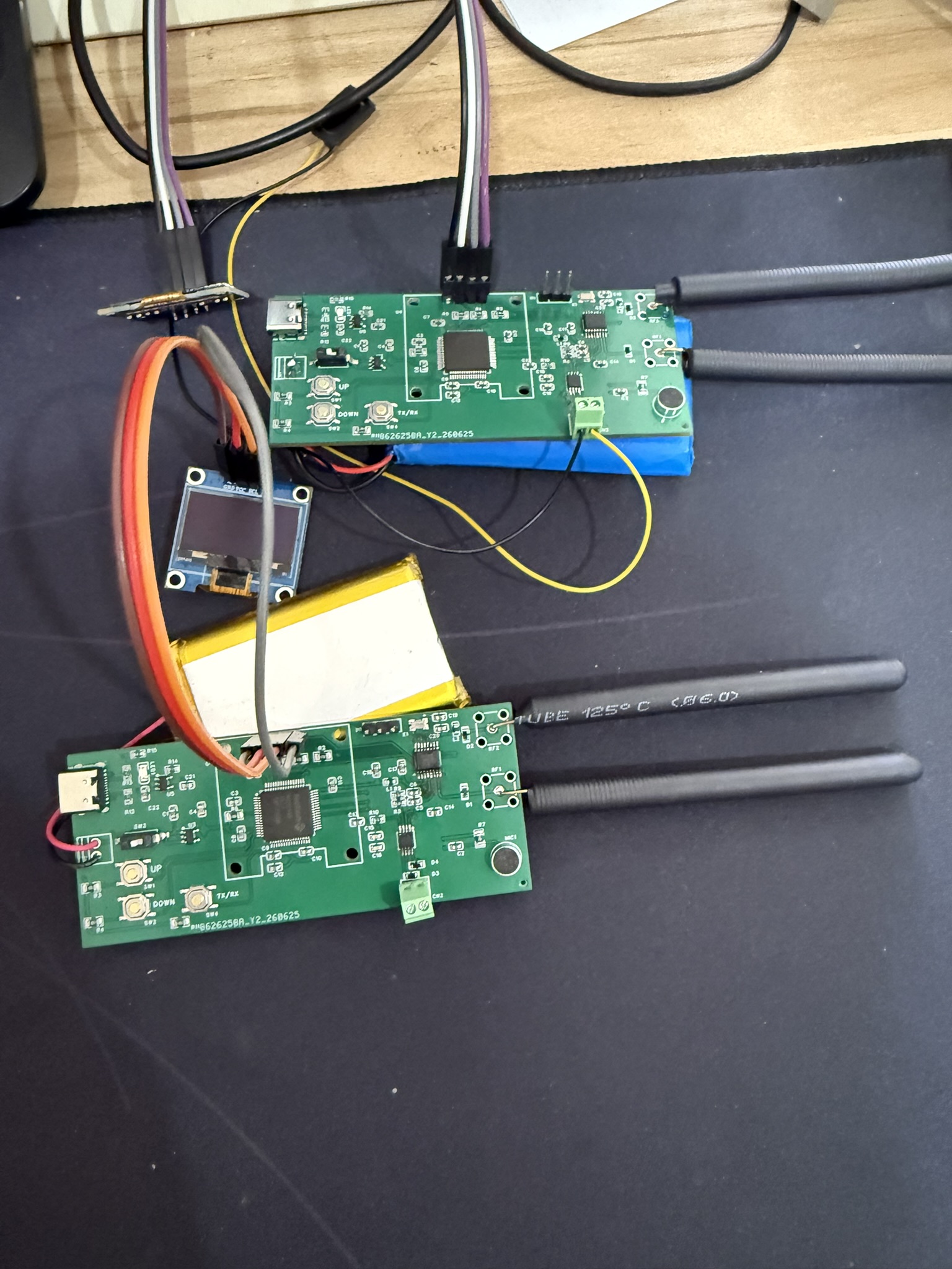
TX and RX boards with QN8066 RF modules, OLED displays, and LiPo power.
Demo: FM audio transmission between TX and RX boards.